Subsonic Wind Tunnel — Design, CFD & Fabrication
OVERVIEW
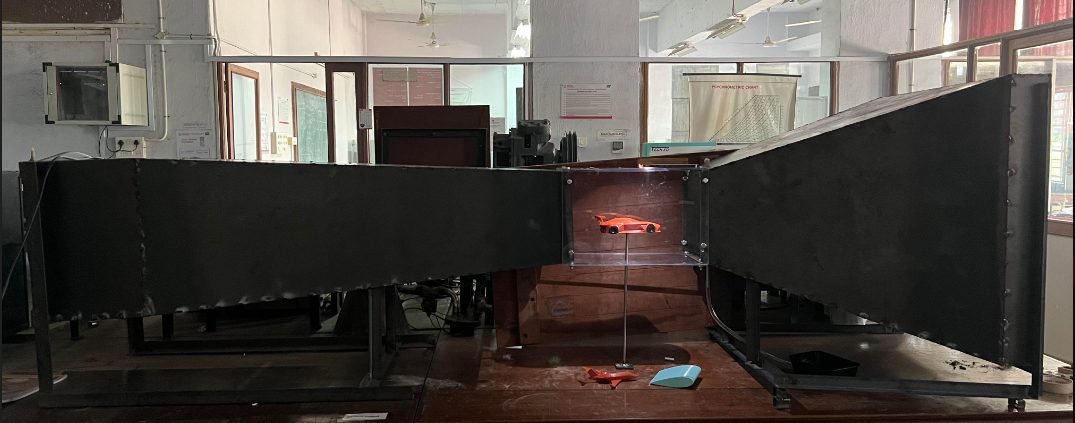
Designed and fabricated an open-circuit, suction-type wind tunnel from first principles — 8.29-ratio contraction cone, hexagonal honeycomb settling chamber, 250×250×400 mm transparent acrylic test section, and diffuser — in SolidWorks, welded steel, and acrylic. Validated in ANSYS Fluent (k-ω, ~836K-node mesh), achieving 9.4 m/s test-section velocity at turbulence intensity as low as 0.42%, confirmed via smoke visualization and anemometer testing on 3D-printed airfoil and vehicle models.
APPROACH
The goal was a working low-speed wind tunnel for flow visualization on small scale models: an aerofoil, a car, and an aircraft. We worked in four stages. First we reviewed the classic design literature (Barlow, Rae & Pope; Mehta & Bradshaw; Bell & Mehta) to pull out the rules of thumb for each component. Then we modeled every section in SolidWorks, checked the assembled geometry with CFD in ANSYS Fluent, and built the tunnel for ₹17,550 (about $210).
KEY DESIGN DECISIONS
Open-circuit, suction type. A closed-circuit tunnel was too big and too expensive for our space and budget. A blower-type tunnel pushes the fan's turbulence straight into the test section, which is only acceptable for rough demonstrations. Putting the fan at the downstream end to pull air through gave cleaner flow, used less power, and made the tunnel quieter and less prone to vibration.
Contraction ratio of 8.29. The inlet is 720 × 720 mm and the test section is 250 × 250 mm. Screen losses fall as 1/c², so a larger ratio is better, but the size, cost, and risk of flow separation rise with it. Small tunnels usually land between 6 and 9, and we sized ours inside that range. A hexagonal honeycomb in the settling chamber straightens the incoming air and removes swirl — we chose the hexagonal shape because it has the lowest pressure drop.
Test section: 400 mm long, clear acrylic. Its length is 1.6 times its hydraulic diameter, inside the recommended range of 0.5 to 3. The model must block less than 10% of the cross-section. We used 6 mm acrylic so the flow could be watched directly, and added a hinged, laser-cut access door so models are quick to swap.
Two-piece diffuser with an area ratio of 2.68. The diffuser widens from 250 mm to 410 mm, inside the 2–5 guideline. This slows the jet before it leaves the tunnel, and splitting it into two pieces made fabrication and assembly easier.
VALIDATING WITH CFD
I meshed the full tunnel at a 10 mm element size, which a mesh-convergence check supported and which kept us under the student license's limit of 1 million nodes. I used the k-ω model because it handles near-wall behavior and adverse pressure gradients well in internal flows. Fluent wouldn't let us set the fan's suction at the true outlet, so I treated the diffuser end as the inlet and gave it a negative velocity, running four cases from 1.8 to 3.0 m/s based on the fan manufacturer's specs.
Across those cases, peak test-section velocity went from 5.6 to 9.4 m/s. Minimum turbulence intensity stayed below 1% but rose with speed, from 0.42% to 0.86%. Pathlines showed smooth, attached flow through the test section.
BUILD
- ▸Contraction and diffuser: 1.5 mm mild steel sheet, cut on a hydraulic press, welded, and sealed with silicone to stop air leaks.
- ▸Fan: a 380 mm Crompton industrial exhaust fan with a speed regulator.
- ▸Models: 3D-printed.
- ▸Measurement: an anemometer for airspeed, and incense-stick smoke with LED lighting to show the flow.
LESSONS
Plan the instrumentation from the start. We aimed to measure lift and drag, but without load cells we were limited to smoke visualization and airspeed readings. Next time I'd design the force balance and sensor mounts into the test section from the beginning.
Alignment is harder than it looks. Joining five separately built sections on one straight axis was the hardest part of the build. Flanges or locating features designed into the CAD would have saved time.
Treat CFD as a design check, not a result. The simulations confirmed the geometry made sense, but they were never compared against measured velocities in the tunnel. Validating one case with the anemometer would have made the results much stronger.
Constraints set the design. The student mesh limit, a ₹17.5k budget, and parts available off the shelf decided about as much as the textbook guidelines did. Learning to design within those limits was the most useful skill I took from this project.